
Chasing Moby Dick
The story of the 1.5V Project is a tale that spans almost the entire length of my obsession with lights.
The short version is that back in 2013 I tried to make a AA light on my new lathe and couldn't find a circuit board to power it. So I thought (in my infinite wisdom): "How hard could it be to make one?"
The long version is that 7 years later, the answer is "Pretty hard".
A little background:
White LED's need 3 volts to operate. AA batteries are 1.5V. A "driver" is a circuit board that boosts the battery voltage from 1.5 to 3V and controls the output, providing brightness levels and such.
There are two ways to dim an LED: constant-current and pulse-width modulation (PWM). If I'd have chosen PWM we probably could have been done with this project back in 2014. :P
Pulse-width modulation blinks an LED really quickly, fooling your eyes into seeing brightness levels when in reality the LED is always full brightness and just turned off sometimes. If you've ever seen a cheap set of Christmas lights flickering at 60Hz - that's PWM.
Constant-current controls the current to the LED, ensuring it's always on but only providing enough power for the desired brightness. There's no blinking or flashing happening. It's certainly the desired way to control an LED, but it's a great deal harder to implement than PWM. The goal with 15VP was constant-current regulation.
PWM (left) vs. constant current (right)
The 15VP driver has been through a number of revisions over the years.
[Version 1] was two separate boards sandwiched together in a brass pill. It had limited range of output, maybe 5-100mA.
[Version 3] was a cool setup - an ATtiny microcontroller and a dedicated FET formed the switching subsystem. Everything was handled in firmware. It worked and had good output (1-400mA) but the codebase was huge and it wasn't particularly efficient.
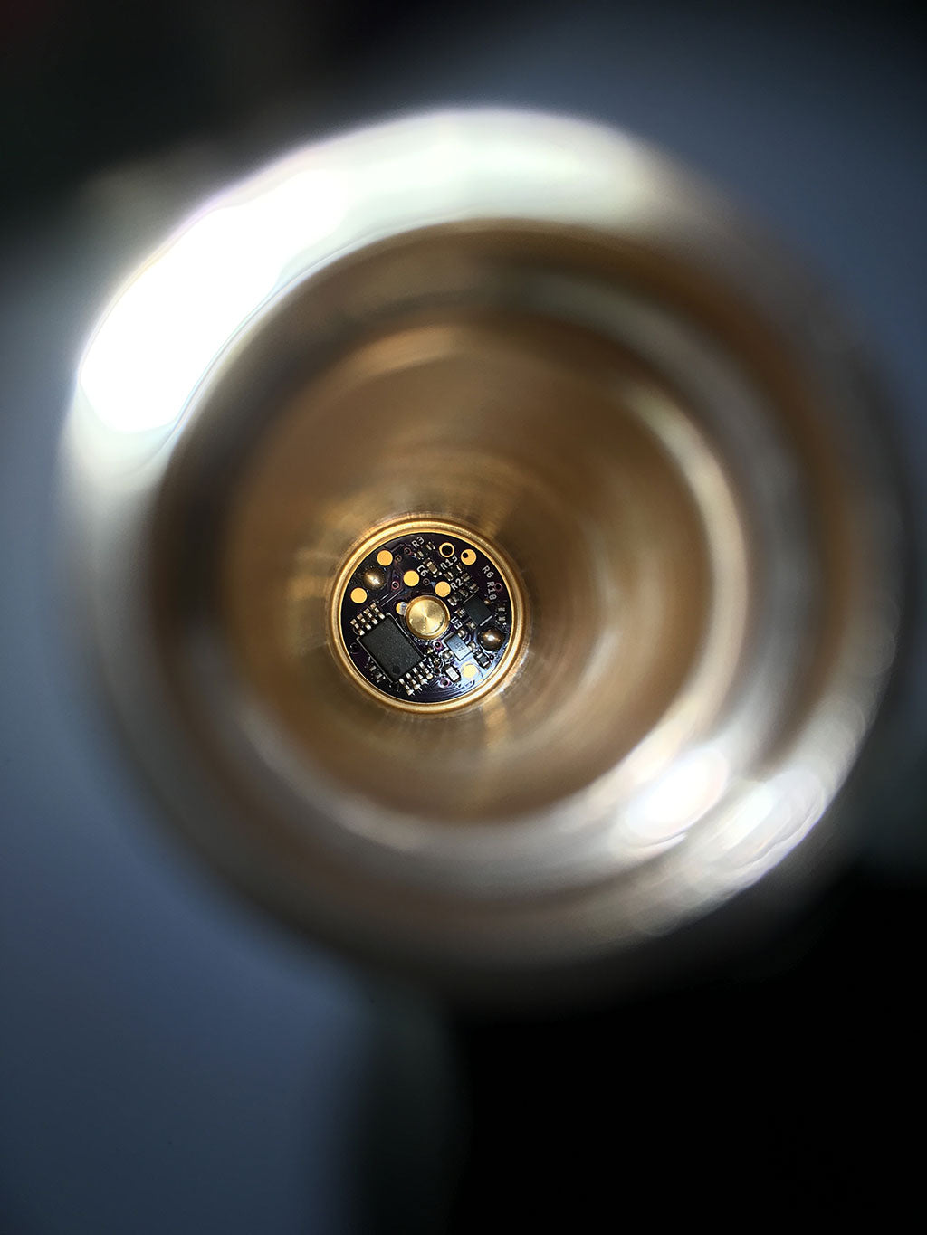
[Version 4] is where we're at today and it's by far the best setup. A dedicated boost IC with synchronous switching (for great efficiency) combined with a constant-current control subsystem controlled by an ATtiny45. It all fits neatly on one single-sided 15mm board. Range of output is good (1-350mA) and all the firmware space is used on cool functionality, not mundane switching operations.
Over many years of evenings & weekends, this project has taught me absolutely everything I know about electronics. From inductor saturation to I2C communications protocols to Ohm's law - it's a ton of great knowledge and the driver's pretty awesome too. :)
You may be wondering why it costs so much! Most overseas drivers cost $3-5. And the answer is that Version 4 was designed with a "no expense spared" thought process. Quite frankly I didn't care how much it cost because I wanted the best, not the cheapest. Just the components alone cost nearly as much as the completed board. And that's not to speak of the labor involved in making each of these things by hand. The tiniest component has pins smaller the lines in your fingerprint. I have to place it between heartbeats.
Should you choose to use the 15VP driver in your LED project, I thank you from the bottom of my heart. It's been a labor of love and I'm beyond happy to finally be able to share it with you. I hope it serves you well for many long years.
Best regards,
Mike